Load factor and maneuvering speed
The V-g diagram, VA, and the structural limits a pilot can exceed with the control wheel alone.
18 min read · Aerodynamics: why the airplane flies
After this lesson you can
- Calculate the load factor of a coordinated, level turn from its bank angle.
- Explain why increased load factor raises the stall speed, using the same critical-AOA logic from earlier in this module.
- Read a Vg diagram: identify the lift-limit curves, the structural limit lines, and VA.
- State exactly what protection VA does and does not provide.
You have never flown an airplane, so you probably assume its structure is built with a huge margin of safety. It is not: every kilogram of extra structure is a kilogram of useful load lost, so a light airplane is engineered close to the limits it will actually see -- and those limits can be exceeded with the control wheel alone, in seconds, with no warning light.
Load factor is the tool that makes those limits legible. The PHAK defines it as the ratio between the lift the wing is producing and the airplane's weight, measured in Gs, the unit of gravitational acceleration. A load factor of 3 means the structure is carrying three times the airplane's weight; a pilot under 3 Gs is pressed into the seat with three times their own weight.
The PHAK gives two reasons every pilot needs this concept. First, it is possible to impose a dangerous overload on the structure. Second -- and this is the one that kills people -- an increased load factor raises the stall speed, so the airplane can stall at airspeeds that feel perfectly safe. This lesson connects the aerodynamics, the structure, and two of the most common accident patterns in general aviation.
1.What load factor actually measures
Load factor, written n, is the ratio of the total lift the wing produces to the airplane's weight. In straight, unaccelerated, level flight, the wing produces exactly enough lift to balance weight: n = 1, or "1 G." Any force applied to deviate the airplane's flight path from a straight line produces a structural load, and load factor is precisely how large that load is.
Load factor is a multiplier, not the load itself. A 2,500-pound airplane at 3 Gs imposes 7,500 pounds on its wings; the same 3 Gs on a 1,200-pound airplane imposes only 3,600 pounds. That is exactly why the structural limit is published in Gs rather than in pounds: it stays valid at any weight up to the airplane's maximum certificated weight.
An accelerometer measures load factor directly, but the PHAK notes that instrument is uncommon on training airplanes. In practice, pilots learn to judge Gs from seat pressure -- the PHAK is explicit that developing this feel is a real skill, since the pressure felt on the controls tells you nothing reliable, because control-system leverage varies from airplane to airplane.
A multiplier, not a weight
Structural load = load factor x actual weight. A 2,200-pound airplane in a 60-degree bank (2 Gs) loads its wings as if it weighed 4,400 pounds. No indicator tells you this is happening -- you have to know it from the bank angle.
2.Why a turn manufactures load factor
In level, wings-level flight, lift is vertical and balances weight directly. The moment you bank, lift tilts with the airplane and splits into two components: a vertical component, which must still equal weight to hold altitude, and a horizontal component, which pulls the airplane toward the center of the turn. Since the vertical component is now only PART of the total lift, total lift has to increase for the vertical part alone to still equal weight.
The result is a precise relationship: load factor in a coordinated, altitude-holding turn equals 1 divided by the cosine of the bank angle. At 30 degrees, that is 1.15 G. At 60 degrees, exactly 2.00 G. At 80 degrees, 5.76 G. The PHAK notes this rate of increase is gentle until about 45 to 50 degrees of bank, then climbs at what it calls a 'terrific rate' -- the curve approaches, but mathematically never reaches, 90 degrees, since a 90-degree-banked, constant-altitude turn is not physically possible.
| Bank angle | Load factor |
|---|---|
| 0 degrees | 1.00 G |
| 30 degrees | 1.15 G |
| 45 degrees | 1.41 G |
| 60 degrees | 2.00 G |
| 70 degrees | 2.92 G |
| 80 degrees | 5.76 G |
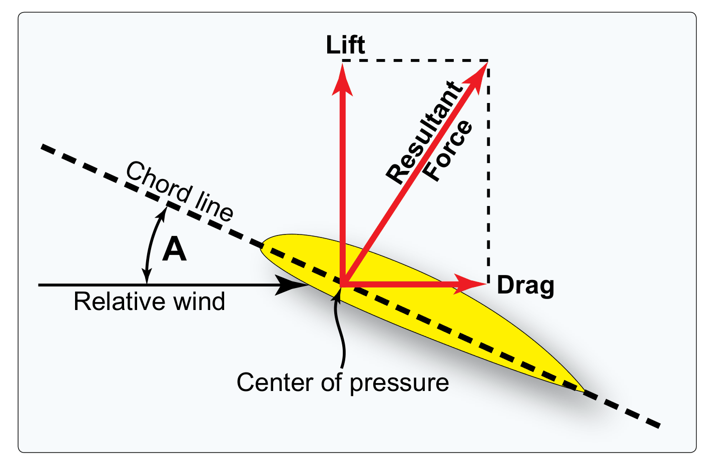
FAA Airman Knowledge Testing Supplement FAA-CT-8080-2H, Figure 1. Lift Vector. A work of the U.S. government, free of copyright. For training only, not for navigation.
Load factor in a turn depends ONLY on bank angle
Not on weight, not on airspeed, not on the type of airplane. A Cessna 152 and an airliner in a coordinated 60-degree bank both pull exactly 2 Gs. The PHAK explains why: at a given bank, faster airplanes turn at a slower rate (fewer degrees per second), and that lower turn rate exactly offsets the extra centrifugal force from the higher speed.
3.The chart the knowledge test will hand you
On test day the FAA does not describe a figure in words: it hands you the figure. Questions on load factor in a turn refer to the plate below, published as Figure 2 of the Airman Knowledge Testing Supplement for the Sport, Recreational and Private Pilot tests (FAA-CT-8080-2H). This is the document itself, not a redrawing of it -- the same colours, the same axes, the same rounding.
Reading it takes one move in each direction. Enter the graph at your bank angle on the horizontal axis, go up to the red curve, and read the load factor on the vertical axis. The table on the left gives the same values exactly rather than approximately, which is what you want when an answer choice differs from its neighbour by a tenth of a G. Notice what the curve does past 60 degrees: between 0 and 30 degrees it is almost flat, and between 80 and 90 it becomes vertical. That shape is the whole lesson in one line.
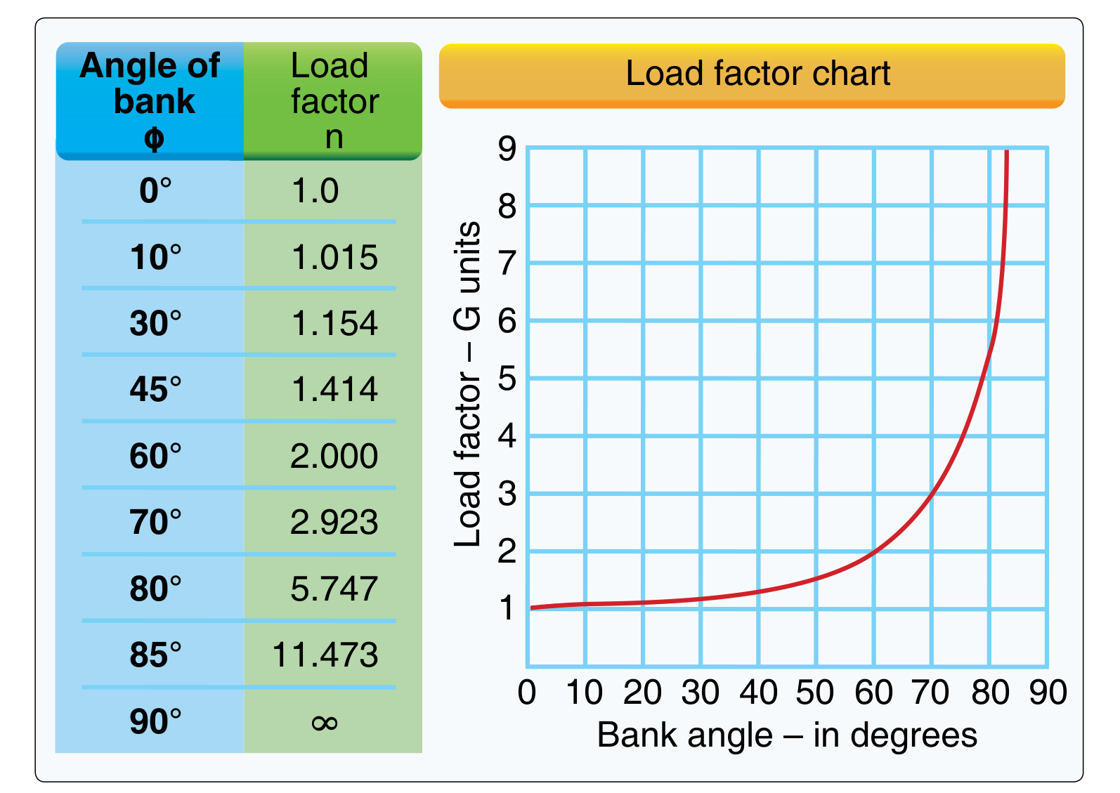
FAA Airman Knowledge Testing Supplement FAA-CT-8080-2H, Figure 2. A work of the U.S. government, free of copyright. For training only.
Know the artifact, not just the formula
Every figure the written test refers to comes from this supplement, and the test names it by number: "Refer to Figure 2." Working from the real plate now means the only thing new on test day is the question.
4.The dangerous consequence: load factor raises stall speed
The wing still stalls at the same critical AOA you studied earlier in this module -- but the AOA needed to produce a given amount of lift depends on speed. If load factor demands more lift, then at any given speed more AOA is needed, so critical AOA (and the stall) is reached at a HIGHER speed than the unaccelerated stall speed.
The relationship is worth memorizing: stall speed increases with the SQUARE ROOT of load factor. The PHAK's own example: an airplane with a normal, unaccelerated stall speed of 50 knots can be stalled at 100 knots if a load factor of 4 Gs is imposed -- and, if it could withstand 9 Gs, it could be stalled at 150 knots. There is no airspeed, within the limits of the structure, at which an airplane cannot be stalled.
The PHAK's second example is the one that kills pilots at low altitude: banking beyond 72 degrees in a level turn produces a load factor of 3. In an airplane with a normal, unaccelerated stall speed of 45 knots, the airspeed must be kept above 75 knots in that turn to avoid a stall. A pilot who has memorized "I stall at 45" and then tightens a turn at low altitude -- to salvage a base-to-final turn, or to circle back after an engine problem -- can stall at a speed that feels completely safe, at a height that does not forgive it.
Quick check
An airplane's normal, unaccelerated stall speed is 60 knots. Under a load factor of 4 Gs, it will stall at approximately:
5.Certification categories and the safety factor
A manufacturer cannot design for the maximum conceivable load -- the PHAK notes those loads are far too high for an efficient design. Instead, regulations require the structure to withstand specific "limit load factors," representing the highest loads reasonably expected in normal operation, without structural damage.
Beyond the limit load factor comes a separate, deliberate safety margin. The limit load is the force that causes permanent deformation; the ultimate load, set at 1.5 times the limit load, is where the material actually breaks. The PHAK is explicit that this 1.5 safety margin "is not something that pilots should willfully abuse" -- it exists to protect against unexpected conditions, not as spare performance to use on purpose.
| Category | Positive limit | Negative limit |
|---|---|---|
| Normal | +3.8 G | -1.52 G |
| Utility (mild acrobatics, including spins) | +4.4 G | -1.76 G |
| Acrobatic | +6.0 G | -3.00 G |
Three numbers worth memorizing
+3.8 / +4.4 / +6.0 G positive, -1.52 / -1.76 / -3.00 G negative. Older airplanes without a category placard, up to about 4,000 pounds gross weight, are treated as comparable to utility category; above 4,000 pounds, their limit load factors decrease with weight and they should be treated as normal category.
6.Reading the Vg diagram
The Vg diagram (the PHAK's name for it; also called a V-n diagram) plots the structural operating strength of one specific airplane, at one specific weight and altitude: indicated airspeed on the horizontal axis, load factor on the vertical axis.
The curved lines are lines of maximum lift capability -- what the wing can aerodynamically produce before it stalls. In the PHAK's own example, an airplane that stalls at 1 G at 64 mph can produce 2 G at 92 mph, 3 G at 112 mph, and 4.4 G at 137 mph, because maximum lift capability grows with the square of airspeed. Above that curve, nothing is aerodynamically possible: the wing stalls before it gets there.
The horizontal lines are the structural limit load factors -- in this example, +4.4 and -1.76 G. Flying above the positive line risks permanent deformation and accelerated fatigue damage, even though the airplane has not yet stalled. The vertical line on the right is the never-exceed speed (redline), 225 mph in the PHAK's example; beyond it, structural failure can occur through several different mechanisms. Everything inside these four boundaries is the safe operating envelope.
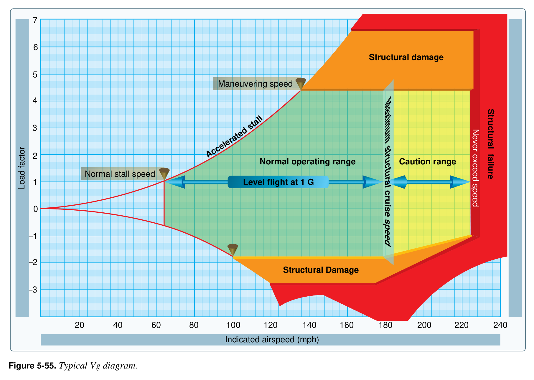
FAA Pilot's Handbook of Aeronautical Knowledge (FAA-H-8083-25C), figure 5-55 - work of the U.S. government, public domain.
7.VA: the point where stalling becomes a structural fuse
The single most important point on the diagram is where the positive lift-capability curve crosses the positive structural limit line. Below that airspeed, the wing stalls before the structure can be overloaded; above it, the wing can generate enough lift to damage the airplane before it stalls. That airspeed is VA, the design maneuvering speed.
The PHAK's definition is precise and every word matters: VA is the speed below which you can move a SINGLE flight control, ONE time, to its FULL deflection, for ONE axis of rotation (pitch, roll, or yaw), in SMOOTH air, without risk of damage to the airplane. Each restriction is load-bearing in the definition.
The corollary is the trap. Operating at or below VA does NOT protect against multiple full control inputs on one axis, or full control inputs on more than one axis at the same time. Rapid, alternating rudder inputs, for example, can overload the vertical fin even below VA -- VA protects against one deliberate full deflection, not against repeated or combined ones.
VA belongs in the AFM/POH
VA must be published in the FAA-approved Airplane Flight Manual/Pilot's Operating Handbook for recently designed airplanes. For older general aviation airplanes without a published VA, the PHAK gives an approximate rule: about 1.7 times the normal stalling speed. An older airplane that stalls at 60 knots should never be intentionally stalled above 102 knots (60 x 1.7). Being stalled at that speed produces a load factor equal to the square of the speed increase: 1.7 x 1.7 = 2.89 G. The PHAK is explicit that these figures are approximations, and that the manufacturer's published numbers govern.
8.VA changes with weight
This is the most counter-intuitive fact in the lesson, and a favorite on the written test: a LIGHTER airplane has a LOWER VA. Intuition says the opposite -- a lighter, less loaded airplane feels like it should be tougher.
The PHAK states the relationship directly: VA may be 100 knots when an airplane is heavily loaded, but only 90 knots when the load is light. The reasoning follows straight from the definition -- VA is where the wing reaches the structural limit load factor exactly at its maximum lift capability, and a given gust or control deflection accelerates a lighter mass more than a heavier one, so the lighter airplane reaches that limit load factor at a lower airspeed.
Quick check
According to the PHAK, how does an airplane's design maneuvering speed (VA) change as the airplane's weight decreases?
9.Load factors documented in real maneuvers
The PHAK ties these ideas together with load factors it has actually documented in specific maneuvers, useful for calibrating your own judgment.
| Situation | Load factor | PHAK note |
|---|---|---|
| Straight, unaccelerated flight | 1.0 G | The only case where load factor stays constant |
| At the moment of a normal stall | near 0 G | The "floating free in space" sensation |
| A properly executed stall recovery | 2 to 2.5 G | A higher load factor should never be necessary except at very low altitude or a near-vertical nose attitude |
| A properly executed spin recovery | about 2.5 G | Recovery is usually made with the nose lower than in a stall recovery |
| Intentional stall at 1.7 x normal stall speed | 3.0 G | A very narrow error margin for light-airplane acrobatics |
| A well-executed chandelle or lazy eight | under 2 G | Beyond 2 G, the altitude gained is actually smaller |
Structural yield arrives before it feels dangerous
The PHAK notes the average light airplane reaches its structural yield point at roughly 70 to 75 degrees of bank, and that each 10 degrees of additional bank beyond 60 degrees adds about 1 G. Between a comfortable 60-degree turn and permanent structural deformation, there may be only about 15 degrees of bank.
What to remember
- Load factor n = lift / weight, in Gs. n = 1 in straight, unaccelerated flight; any deviation from that flight path raises n.
- In a coordinated, altitude-holding turn, n = 1 / cos(bank angle) -- depends only on bank angle, not weight or airspeed. 60 degrees is exactly 2.00 G.
- Stall speed rises with the square root of load factor. A 50-knot airplane stalls at 100 knots under 4 Gs -- there is no speed at which an airplane cannot be stalled.
- Category limit load factors: normal +3.8/-1.52 G, utility +4.4/-1.76 G, acrobatic +6.0/-3.00 G. The structure survives 1.5x these values without breaking, but with permanent deformation -- that margin is not a reserve to use on purpose.
- VA is a partial fuse: below it, ONE full control deflection on ONE axis in smooth air will not damage the airplane -- but repeated or multi-axis inputs can, even below VA.
- VA falls as weight falls. Slow to the VA appropriate for today's actual weight in turbulence, not the placarded value at maximum weight.
Key terms
Try to recall each definition before turning the card.
FAA sources for this lesson
- PHAK (FAA-H-8083-25) Chapter 5 -- Aerodynamics of Flight, "Load Factors," "Load Factors in Steep Turns," "Load Factors and Stalling Speeds," "Load Factors and Flight Maneuvers," "Vg Diagram" (pp. 5-33 to 5-38)
- PHAK Figure 5-53 -- Angle of bank changes load factor in level flight
- PHAK Figure 5-54 -- Load factor changes stall speed
- PHAK Figure 5-55 -- Typical Vg diagram
- PHAK Chapter 8 -- Flight Instruments, "Design maneuvering speed (VA)" (pp. 8-9 to 8-10)
End-of-lesson quiz
1.In a coordinated, altitude-holding turn at 60 degrees of bank, the load factor is:
2.A structural limit load factor of +4.4 G belongs to which certification category?
3.Flying at or below VA guarantees that:
4.As an airplane's actual weight decreases below its maximum certificated weight, its design maneuvering speed VA:
5.On the Vg diagram, the point where the positive lift-capability curve crosses the positive structural limit line defines: